- 您现在的位置:买卖IC网 > Sheet目录985 > IRPLLED1 (International Rectifier)BOARD EVALUATION FOR IRS2540PBF
�� �
�
�IRS254(0,1)(S)PbF�
�form� the� voltage� clamp.� The� repetition� of� the� spikes�
�100�
�90�
�80�
�70�
�60�
�50�
�40�
�30�
�20�
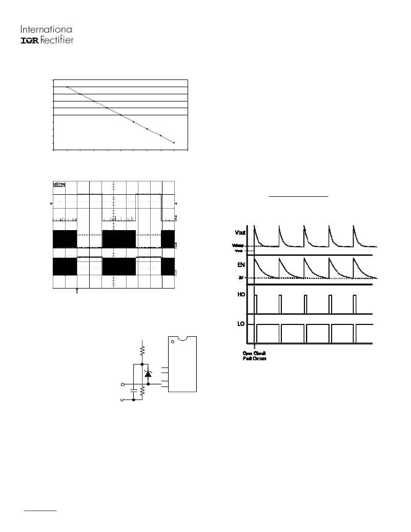
�Enable� Duty� Cycle� Relationship� to� Light� Output�
�can� be� reduced� by� simply� increasing� the� capacitor�
�size.�
�The� two� resistors� form� a� voltage� divider� for� the�
�output,� which� is� then� fed� into� the� cathode� of� the�
�zener� diode.� The� diode� will� only� conduct,� flooding�
�the� enable� pin,� when� its� nominal� voltage� is�
�exceeded.� The� chip� will� enter� a� disabled� state� once�
�the� divider� network� produces� a� voltage� at� least� 2.5� V�
�greater� than� the� zener� rating.� The� capacitor� serves�
�10�
�0�
�0�
�10�
�20�
�30�
�40�
�50�
�60�
�70�
�80�
�90�
�100�
�only� to� filter� and� slow� the� transients/switching� at� the�
�positive� output� terminal.� The� clamped� output�
�Percentage� of� Light� Output�
�Fig.5� Light� Output� vs� Enable� Pin� Duty� Cycle�
�voltage� can� be� determined� by� the� following� analysis.�
�The� choice� of� capacitor� is� at� the� designer’s�
�discretion.�
�EN�
�V� out� =�
�(� 2 .5� V� +� DZ� )(� R� 1� +� R� 2� )�
�R� 2�
�DZ� =� Zener� Diode� Nominal� Rated� Voltage�
�HO�
�LO�
�Fig.6� IRS254(0,1)� Dimming� Signals�
�Open� Circuit� Protection� Mode�
�By� using� the� suggested�
�voltage� divider,�
�capacitor,� and� zener�
�diode,� the� output�
�Vout�
�R1�
�voltage� can� be� clamped�
�at� any� desired� value.� In�
�open-circuit� condition�
�without� output� clamp,�
�the� positive� output�
�R2�
�IFB�
�EN�
�3�
�4�
�Fig.8� Open� Circuit� Fault� Signals,� with� Clamp�
�Under-voltage� Lock-out� Mode�
�terminal� will� float� at� the�
�high-side� input� voltage.�
�Fig.7� Open� Circuit�
�Protection� Scheme�
�Switching� will� still� occur�
�between� the� HO� and� LO�
�outputs,� whether� due� to� the�
�output� voltage� clamp� or� the� watchdog� timer.�
�Transients� and� switching� will� be� observed� at� the�
�positive� output� terminal� as� seen� in� Fig.� 8.� The�
�difference� in� signal� shape,� between� the� output�
�voltage� and� the� I� FB� ,� is� due� to� the� capacitor� used� to�
�www.irf.com�
�The� under-voltage� lock-out� mode� (UVLO)� is� defined�
�as� the� state� IRS254(0,1)� is� in� when� V� CC� is� below� the�
�turn-on� threshold� of� the� IC.� During� startup�
�conditions,� if� the� IC� supply� remains� below� V� CCUV+� ,� the�
�IRS254(0,1)� will� enter� the� UVLO� mode.� This� state� is�
�very� similar� to� when� the� IC� has� been� disabled� via�
�control� signals,� except� that� LO� is� also� held� low.�
�When� the� supply� is� increased� to� V� CCUV+� ,� the� IC� enters�
�the� normal� operation� mode.� If� already� in� normal�
�Page� 9�
�发布紧急采购,3分钟左右您将得到回复。
相关PDF资料
ISDCB824
CABLE RIBBON 24"
ISL29000IROZ-EVALZ
EVALUATION BOARD FOR ISL29000
ISL29001IROZ-EVALZ
EVALUATION BOARD FOR ISL29001
ISL29002IROZ-EVALZ
EVALUATION BOARD FOR ISL29002
ISL29003IROZ-EVALZ
EVALUATION BOARD FOR ISL29003
ISL29008IROZ-EVALZ
EVALUATION BOARD FOR ISL29008
ISL29009IROZ-EVALZ
EVALUATION BOARD FOR ISL29009
ISL29010IROZ-EVALZ
EVALUATION BOARD FOR ISL29010
相关代理商/技术参数
IRPLLED1A
功能描述:电源管理IC开发工具 Hi-Vlt DC-DC Buck Cnvr HBLED Cur Cntrl RoHS:否 制造商:Maxim Integrated 产品:Evaluation Kits 类型:Battery Management 工具用于评估:MAX17710GB 输入电压: 输出电压:1.8 V
IRPLLED5
制造商:International Rectifier 功能描述:
IRPLLED7
功能描述:IC MOSFET DRIVER RoHS:否 类别:集成电路 (IC) >> PMIC - MOSFET,电桥驱动器 - 外部开关 系列:* 标准包装:95 系列:- 配置:半桥 输入类型:PWM 延迟时间:25ns 电流 - 峰:1.6A 配置数:1 输出数:2 高端电压 - 最大(自引导启动):118V 电源电压:9 V ~ 14 V 工作温度:-40°C ~ 125°C 安装类型:表面贴装 封装/外壳:8-SOIC(0.154",3.90mm 宽) 供应商设备封装:8-SOIC 包装:管件 产品目录页面:1282 (CN2011-ZH PDF) 其它名称:*LM5104M*LM5104M/NOPBLM5104M
IRPLLNR1
制造商:未知厂家 制造商全称:未知厂家 功能描述:
IRPLLNR2E
功能描述:KIT BALLAST LINEAR INT 230VAC RoHS:否 类别:编程器,开发系统 >> 过时/停产零件编号 系列:- 标准包装:1 系列:- 类型:MCU 适用于相关产品:Freescale MC68HC908LJ/LK(80-QFP ZIF 插口) 所含物品:面板、缆线、软件、数据表和用户手册 其它名称:520-1035
IRPLLNR2U
功能描述:BALLAST 32W/T8 120V AC IR21571 RoHS:否 类别:编程器,开发系统 >> 过时/停产零件编号 系列:- 标准包装:1 系列:- 类型:MCU 适用于相关产品:Freescale MC68HC908LJ/LK(80-QFP ZIF 插口) 所含物品:面板、缆线、软件、数据表和用户手册 其它名称:520-1035
IRPLLNR3
制造商:IRF 制造商全称:International Rectifier 功能描述:Universal Input Linear Fluorescent Ballast using the IR2167
IRPLLNR4
功能描述:BALLAST UNIV INP FLUOR IR2166 RoHS:否 类别:编程器,开发系统 >> 过时/停产零件编号 系列:- 标准包装:1 系列:- 类型:MCU 适用于相关产品:Freescale MC68HC908LJ/LK(80-QFP ZIF 插口) 所含物品:面板、缆线、软件、数据表和用户手册 其它名称:520-1035